back
Project Documentation
Table of Contents
Introduction
I. Given Data
a. 2D Floorplans
i. Location
ii. Organization and Nomenclature
iii. Floorplan Contents
vi. Doors and Windows
v. Problems
b. Gehry Files
II. Preliminaries
a. Requirements
b. General Process
i. Osnaps
ii. Layers
iii. Exporting the Model
III. Geometries and Structures
a. Vertical Elements
i. Planar
ii. Non-Planar
b. Non-vertical Elements
i. Planar
ii. Non-Planar
c. Repeated Elements
i. Office Facades
ii. Stairs
iii. Railings
iv. Glass Panels
v. External Windows
IV. AutoLISP
a. How it Works
b. Functions
V. Current Status
a. Unsolved Problems
i. Offices
ii. Electrical Rooms, Janitor Closets, and Other Locked Rooms
iii. Helical Stairs
iv. Student Street and Area Above It
v. Objects on Ceilings
vi. Moldings
a. Floor by Floor Progress
i. First Floor
ii. Second Floor
iii. Third Floor
iv. Fourth Floor
v. Fifth Floor
vi. Sixth Floor
vii. Seventh Floor
viii. Eight Floor
ix. Ninth Floor
During summer 2006, we (Xiao Xiao and Tiffany Li) worked on a UROP to build a 3D model of the Stata Center. We built the model in AutoCAD2007 starting with detailed, pre-made 2D floorplans. From the 2D floorplans, we made many field measurements with a laser range finder and tape measurers in order to model 3D elements such as walls, windows, floors, and ceilings. This is a documentation of our project.
Section one describes the data that we were given—where it is, what is available, how it is organized, and what problems there.
Section two defines the requirements that we must satisfy with our model along with the tools that we used. It also includes a brief description of how we went about our work in order to satisfy the constraints.
Section three explains the phases of our work based on the various geometries that we encountered. It describes the problems we faced and analyzes various solution approaches that we took.
Section four documents the code that we wrote to simplify the modeling process
Section five details the current status of the project and includes some problems that we still face.
For any questions, please contact Xiao Xiao (x_x@mit.edu)
back to top
i. Location
The 2D floorplans that we used are found at: http://isis.lcs.mit.edu/Stata_Drawings, which requires a password to enter.
They are in the directory: 01CDs/CDs_Stata/Issue12_021003/02100301_arch_iss12/.
ii. Organization and Nomenclature
Files that begin with FP are the main floor plans that we used. The number at the end of the FP files denotes the floor that the file documents. For example, FP_03.DWG is a map of the third floor. Note that there is no FP_02 because the second floor and the first floor are in the same file (FP_01). Generally, when a file ends with a number 0x, the x denotes the number of the floor.
Other files in the directory include:
CP_0x - ceiling plans
FPC_0x- concrete pillars
FPR_0x- elevator maps
FPT_0x- labels for names of rooms and doors
FP_0x- includes ceiling pipes and hanging lights locations
PEF_0x- doors and windows (see following section)
SP_xx- surroundings of Stata
The FP files make external references to some of these files. When viewed in AutoCAD, the FP files will be missing areas if the external reference files are not downloaded into the same directory as the FP’s. The names of the necessary files are shown on the command line when the FP files are opened.
iii. Floorplan Contents
All the FP files are cut at 48 inches above the ground. Sometimes, they also include traces for the floor and ceiling when there are floating elements or when walls are non-vertical.
iv. Doors and Windows
The floorplan site also includes drawings of walls with doors and windows. These are found in the files that begin with PEF. Each PEF file has drawings for many office facades. They are labeled at the bottom. These labels correspond to the labels found in the FPT files.

This is a drawing of some office facades. The label is at the bottom left corner
v. Problems
We have discovered some significant errors in the floorplans. The lines for the vertical walls are generally reliable, but some of lines for non-vertical walls, the non-planar ones especially, are sometimes off by close to a foot. Also, there a few areas where the floorplan is completely different from the actual building. This is especially apparent in the basement.
b. Gehry Files
The Frank Gehry office has provided us with a detailed exterior model of the Stata Center. We plan to compare our finished model with it to check for errors.
back to top
The 3D model of the Stata Center must satisfy certain properties. First, it must be manifold, which means that every edge of a face must be shared by one and only one other face. Therefore, the model must not have intersecting faces or faces that with edges not shared by other faces. In addition, the surface normals for the faces must be in the correct direction, or rather in the direction that points to the viewer. That means that all the interior walls must have their surface normals pointing inward. The way the surface normal of a face points is determined by the order its vertices are defined, which is governed by the Right Hand Rule.
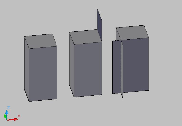
In this image, only the left-most object is manifold. The middle one has a protruding face, and the right-most one has intersecting faces."
back to top
We used AutoCAD 2007 to build this 3D model. In AutoCAD, we modeled all surfaces as 3dfaces. 3dfaces are defined by three of four vertices. The way the surface normals point depends on the order these points are defined.
i. Osnaps
In order to make sure our model is manifold and does not have any gaps between faces, we turned on the OSNAP option in AutoCAD such that we can snap to previously made points when making new faces. However, one should be aware that sometimes, the osnaps has some glitches when it is used with AutoLISP functions. Sometimes, AutoCAD automatically snaps to points that it should not. The solution to that is to zoom in to a very small area when the function is about to generate objects to prevent AutoCAD from seeing extraneous points to snap to.
ii. Layers
AutoCAD allows users to put separate a model into layers. For the sake or organization, our model was done in many layers. We had a layer for walls, floors, ceilings, windows, stairs, etc. For some parts of the model, we had different layers for different colors of carpet. In other words, we placed objects made from different materials on different layers. We also had a temporary layer (temp) where we drew guidelines to help us model other objects. Using layers is not essential for the model, for objects no longer exist on separate layers when exported. However, it simplifies the process because one can always turn off layers for easier access to other parts of the model and to minimize AutoCAD's lag time. This is especially useful in the later stages of the project when maintaining everything in the model on the screen at the same time causes AutoCAD to run unbearably slowly.
iii. Exporting the Model
The AutoCAD DWG model can be harvested into a more widely compatible format that can be viewed in various 3D viewers. To do that, we selected all the faces of our model, and used the LIST command within AutoCAD to obtain a list of all the selected elements with their properties. In this list, 3dfaces are written in terms of their vertices. This file is then fed through a C++ program written by Olivier Koch, which outputs 3 files—faces, edges, and vertices—in a format that can be read by 3D viewers.
back to top
i. Planar
This is the simplest geometry found in Stata and the first that we worked on. Vertical walls are modeled using a function that we wrote, which takes in a height and ground points and generates the vertical wall part by part. For more information about the functions that we wrote, see section IV.
Floors and ceilings are generated using the floor and ceiling functions, which takes in either two (opposite corners), three, or four points and generates the a face at the correct height.
ii. Non-Planar
Vertical non-planar walls are not much more difficult to model than vertical planar walls because it is nothing more than a series of narrow, planar walls. The non-vertical walls are drawn as polylines on the floorplan. To model them, we used the same wall function as the vertical planar walls and clicked on more points along the polylines.
The floor and ceiling along non-planar walls are slightly more complicated than the ones along planar walls because they can no longer be divided into easy to model rectangles. We wrote a function that takes a vertex and a list of points and draws many triangles emanating from the vertex. This function is useful in covering large areas with “curved” boundaries. For fill gaps, we drew some faces by hand.
We treated vertical pillars the same way we treated vertical walls.
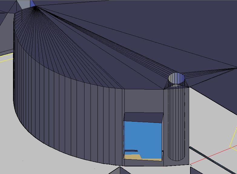
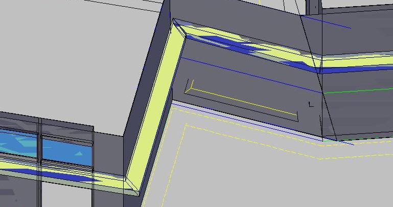
This is an example of vertical non-planar geometry. Note how the wall consists of narrow strips of planar walls and how the ceiling largely consists of triangles emanating from vertices. A column can be seen on the right side of the picture through a section of wall. Note how it is modeled using the same technique as the wall.
back to top
i. Planar
For non-vertical, planar walls, we found the two endpoints of the wall on the ground by doing some measurements from known points. Then, we plugged those points, the given points cut at 48 inches, and the vertical height of the wall into a convex combination function, which drew the slanted wall.
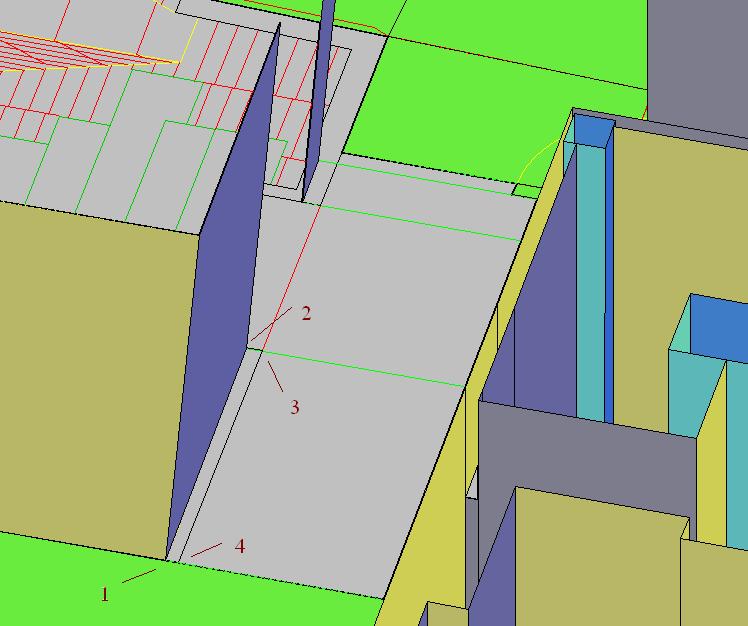
The blue wall is an example of a non-vertical wall. The numbers 1-4 refer to the points inputted into the convex combination function, which were clicked in that order. The function then proceeded to draw the wall.
ii. Non-Planar
Most of the time, the floor and/or ceiling traces are given for non-vertical, non-planar surfaces, so we could use them as a guide in drawing our walls. When both the floor and the ceiling traces are present, we used a function which took in a list of the top points and a list of the bottom points and drew walls connecting them. When we had two traces but not both the floor and the ceiling, we used a modified version of the convex combination function.
back to top
There are many repeated structures in the Stata Center. For most of these, we modeled one instance, saved it in a separate file, and copy-pasted it wherever it occurred in the model. This section describes some of the repeated elements that we have modeled. However, not all of these elements are completely modeled within Stata, and not all of the methods of modeling are completely developed and optimized.
i. Office Facades
We used the PEF files as a base to model the windows on the facades of offices. We also modeled the walls above and below the windows in the separate file. We did not include doorframes in these files because we modeled those before we modeled the office windows. For a discussion of doorframes, see the code section. In hindsight, it would have been faster if we had included the doorframes with the rest of the office facade.
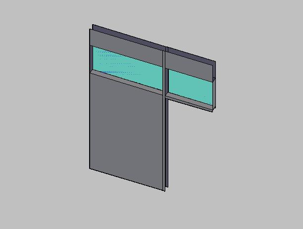
This is a model of an office facade.
back to top
ii. Stairs
Most of the stairs in the Stata Center are standardized. For these, we modeled a single step and copy-pasted strings of this step together to model chunks of stairs.
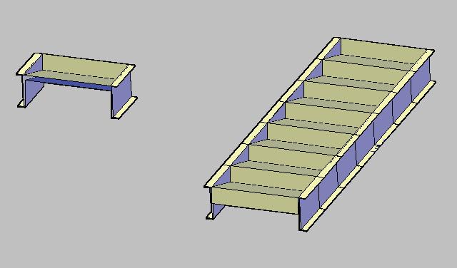
On the left is a single step that we have modeled. The chunk of stairs on the right was made by putting together several of the step modules on the left.
We modeled the non-standard (curved) stairs by hand using the traces given the by the floorplans.
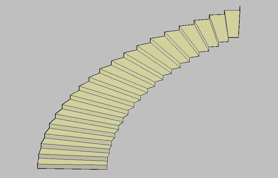
This is a section of curved stairs that we modeled. Only the top surface of this particular stairway is complete.
For a discussion of helical staircases, see section five.
back to top
iii. Railings
There are three types of railings- straight, slanted, and curved. This summer, we have only started modeling straight railings on the third floor of Stata. Railings are tricky to model because the spaces between the small rails are not completely even. Although these differences are small, they add up for long strip of railing and cause significant errors. For certain parts of the railing, we have only modeled the horizontal metal strip at the very top because that is the most visually prominent part of the railing.
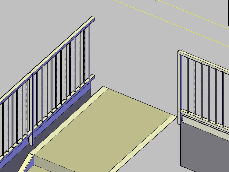
This is a section of railings with details.
This is a section of railings with only the top metal strip drawn.
back to top
iv. Glass Panels
Glass panels, or glass walls occur at many places inside Stata. Initially, we modeled these the same way we modeled normal vertical, planar walls. However, because there are many visually prominent metal beams that support the glass panes, it is necessary to model the individual metal beams as well.
We have begun changing the old version into the new version with the metal beams. To do so, we used a function that draws small chunks of vertical beam and a function that draws small chunks of horizontal beam. The actual glass is now omitted because it is transparent. However, this method is still very time consuming. Because these walls are fairly standardized, one could probably write an even more convenient function to generate the beams. In addition, one should note that this is still a simplified method of drawing these walls because the actual beams have ridges that are not present in the model. That said, it may not be necessary to model the beams in all their detail since from a distance, their shape are very well approximated by our new version of the model.
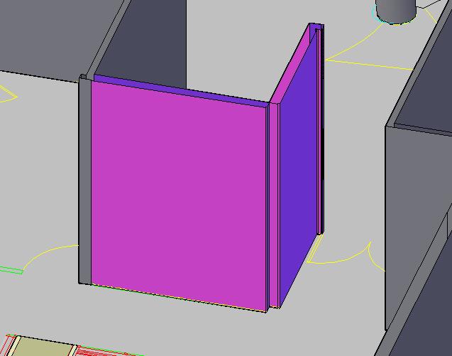
The pink wall represents a glass wall. This is the old way we modeled glass walls.
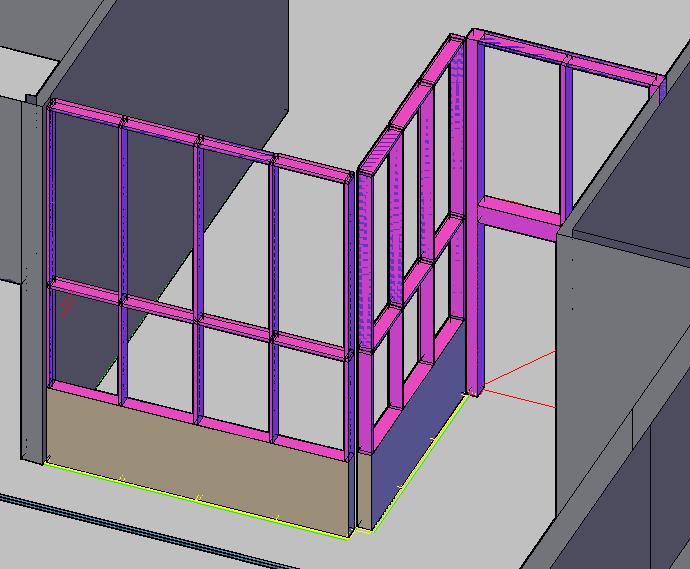
This is the new way that we are modeling glass walls. Again in pink, the wall's visually prominent metal beams can now be seen. This image shows the same wall as the previous image with a bit more of the wall modeled.
back to top
v. External Windows
For documentation on interior windows, such as the ones found above the doors of offices, see section office facades.
We settled on a method to model these windows using a function, which takes in four points and draws the entire window. The function works for windows on vertical as well as non-vertical walls.
We left out a lot of the detail on these windows. First, these windows have a wooden surface on the bottom that extend about an inch beyond the wall. We modeled these in the windows that we drew in the before we wrote the function but omitted them later on in the project. Thus, some of the wall windows lack this wooden detail, which should probably be added later. In addition, the windowpanes themselves are surrounded by metal frames with handlebars to open the windows. We excluded these details entirely and only modeled the windowpane as a single face.
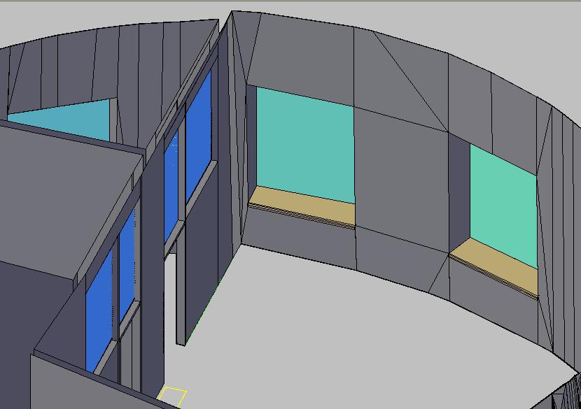
This is the way we initially modeled these windows. Note the brown panel at the bottom. These windows were modeled by hand because the wall in which they are embedded is curved.
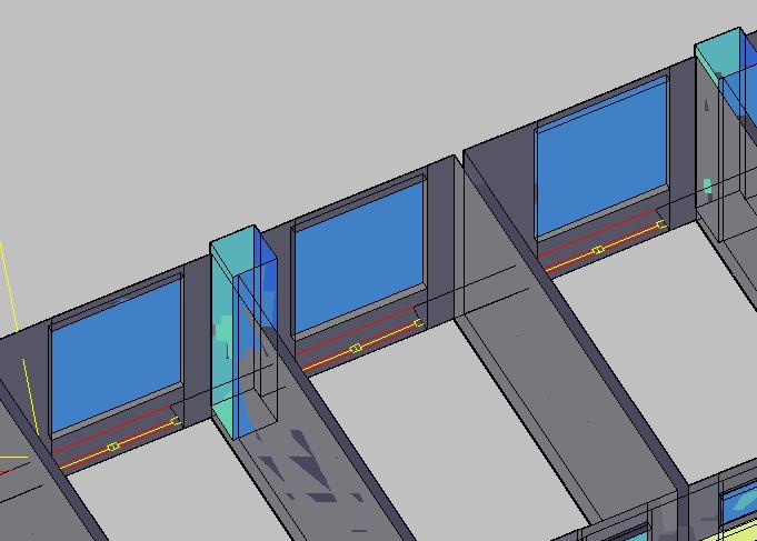
Here is a row of windows generated using our window generating function.
back to top
vi. Light-Holders
Metal light-holders occur along many of the walls in Stata. Although the top of these objects are actually concave in order to fit the light fixtures in there, we have modeled the top surfaces as flat. We used a function to generate these.
The light-holder is the structure in lime-green.
back to top
AutoCAD allows users to code new functions using AutoLISP. This was useful for us because we had to model many elements that were repetitive but were not identical such that we could not just copy-paste them. AutoLISP is not powerful enough to allow us to generate the entire model from code. Points still had to be specified, and many measurements still had to be made. However, it did automate a part of the process and cut down a portion of repetitive work.
AutoCAD comes with its own AutoLISP editor. This can be accessed under Tools>AutoLISP>Visual LISP editor. To import an AutoLISP file, one should go to Tools>AutoLISP>Load Application and select the chosen .LSP files.
Here is a sample AutoLISP function:
(defun c:test ( / p1 p2)
  (setq p1 (getpoint "enter a point"))
  (setq p2 (getpoint "enter another point"))
  (command "line" p1 p2 ""))
Once loaded, this function is called in AutoCAD by typing "test". It then asks for two points and draws a line between the points.
Here is a list of AutoLISP elements illustrated by the example:
* defun- defines a function
* c:test- the name of the function. The C: is necessary in front of the name in order to make it a function that can be called within AutoCAD.
* ( / p1 p2)- a list of variables used in the function. Variables before the slash are arguments to the function (there are none here). Variables after the slash are internal variables. It is not necessary to declare them at the beginning, but it promotes neatness, especially for longer functions.
* (command ...)- performs an AutoCAD command. "" is the same as pressing enter or the space bar in AutoCAD.
For a more comprehensive guide to AutoLISP, see the AutoLISP help file.
back to top
useful.LSP- Contains functions that are used multiple times by other functions including abstractions. We load this file before loading any others.
The rest in alphebetical order:
ceiling.LSP- Called by typing "ce", this function initially sets the "ceiling" layer as the active layer. If there is no ceiling layer, one is created. Next, it asks for the height of the ceiling above the ground. If a negative number is entered, it prompts the user to select two points the distance between which are then used for height. It then prompts the user to click on points in the floorplan. If two points are entered before pressing enter, a rectangular patch of ceiling is drawn with the two points as corner points. If three points are entered, a triangular patch is drawn; if four, a quadrilateral is drawn. The user may keep entering two, three, or four points, pressing enter afterwards to continue drawing ceiling patches at the given height. To end the function, press esc or enter twice without selecting points. Note that the for the two point rectangle to work, the coordinate system must be lined up with where you want the rectangle. For the three or four-point options, make sure that the points are selected in such an order such that the surface normals are pointing in the correct direction. Also note that when we modeled large sections of ceiling with uniform height, we modified the source code of the function such that it automatically draws the ceiling a specified height instead of prompting every time for a number.
convex-combo.LSP- Called by typing "cc", first prompts for the height of the wall. Then, it asks for the boundary points of the wall at ground and at 48 inches found in the floorplan. The function takes only the xy-coordinates of selected points and plugs in the correct values for the z-coordinates. It then calculates the tilt and/or slant of the wall and draws in the model. When we modeled large sections where the walls were the same height, we usually changed the source code of the function such that it automatically draws the walls to a certain height instead of prompting it every time.
cv.LSP- Called by typing "cv", used to draw floor and ceiling areas for rooms with curved walls. This function first asks for a height and a vertex point from the floorplan. It then asks the user to enter a row of points from the floorplan, which it uses to make triangular faces emanating from the vertex. For a image of what this looks like, click here.
cw.LSP- Called by typing "cw", used to draw windows that look to the outside. Since most of these windows occur in the upper floors where the height of the room is standard, specified the height of the room within the function. This function asks for eight points on the floorplan and then draws the entire window.
floor.LSP- Called by typing "fl", this function is exactly the same as ceiling.LSP except that it does not prompt for a height but draws all chunks of floor at height zero. Also, it is necessary to make sure that the surface normals are pointing in the right direction when selecting three of four points. They should be selected in the opposite order as for ceiling.LSP.
doorframe.LSP- Called by typing "df", this function asks for the four corner points of a door frame on the floorplan and draws the three faces consisting of the door frame.
lp.LSP- Called by typing "lp", this function asks for the four corner points of a section of light holder on the floorplan and draws a horizontal tube made of four faces at a specified height. We found it easier to specify the height in the function and to change that height within the code occasionally instead of having the function ask for a height every time.
vb.LSP- Called by typing "vb", this function asks for four points on the floorplan and draws a vertical tube of the correct length and at the correct height. Again, both the length and the height are specified in the function.
w2.LSP- Called by typing "w2", this function asks for two rows of points, one row on top of another, and connects these points with a series of walls.
wall.LSP- Called by typing “wa”. It prompts the user to enter a height for the wall. If a negative number is entered, it allows the user to input a height by taking the distance between two selected points. It then prompts the user for ground points on the floorplan and proceeds to extrude walls along the points clicked. Pressing enter or esc ends the function.
Alternatively, if a section of the building has many walls of the same height, we modified this function such that it draws all walls at a specified height and does not keep prompting for a height every time you call the function.
To check what direction the surface normal is pointing, hold your right hand palm up in the direction of your selected points. The surface normal points to the direction of your thumb.
back to top
i. Offices
Most of the offices within Stata have vertical walls and can be modeled without doing any measurements inside. However, there are some offices that have unusual non-vertical geometries. With the exception of a couple of offices, these need to be measured and modeled.
These offices are a particular challenge because many professors have a lot of furniture that obstruct measurements and cannot be easily moved.
ii. Electrical Rooms, Janitor Closets, and Other Locked Rooms
We have not done these not because they are difficult but because we did not have time. These should have vertical walls. The one thing that needs to be checked is the height of the ceilings. It is necessary to ask TIG for the keys to gain access to these rooms.
iii. Helical Stairs
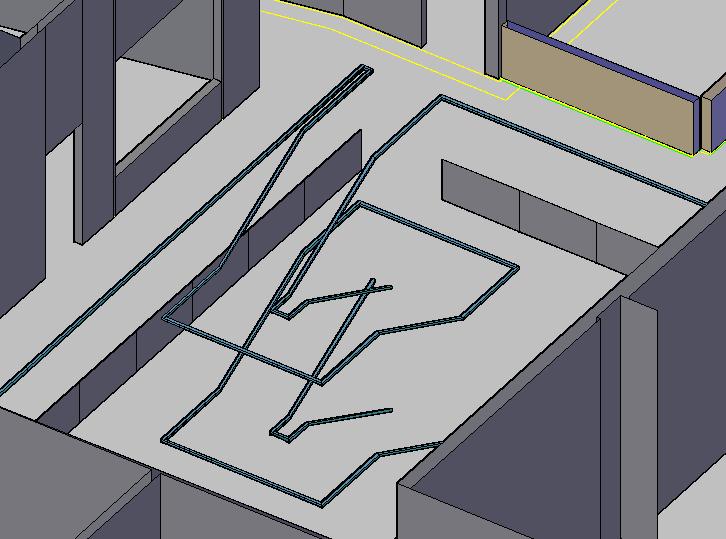
There is one helical staircase that is repeated several times in the two towers. We have already modeled it, but it is modeled using objects in AutoCAD which cannot be translated using Olivier Koch’s program.
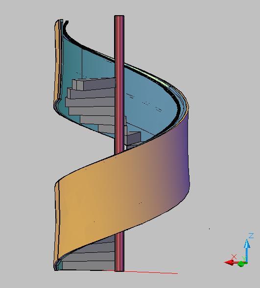
This is the helical staircase that we have modeled.
vi. Student Street and Area Above It
We have begun modeling the student street, starting from the cafeteria. At least between 60-70% of the walls on the Student Street are drawn, but we are missing some of the more difficult geometries such as anomalies on the ceilings. As for the area above the Student Street on the third floor, we have modeled the areas by the elevators and the curved stairs going between the first and third floors. The various landings and balconies on the third floor are not modeled yet.
v. Objects on Ceilings
There are many visually prominent features located on the ceilings of Stata such as pipes and lights. We have not modeled any of these. The XY location of these features can be found in the FR files. It will probably not be too difficult to write a function to generate these given their distance above the ground. As for the lights on the ceilings, they can be treated as a repeated element that can be copy-pasted to their appropriate locations.
There are also patches of the ceiling where a flat panel is extended a few inches lower than the actual ceiling. We did not model these ceiling panels.
vi. Moldings
We have omitted the moldings that surround doors and windows thus far. One can probably write a function to help generate these in the future.
back to top
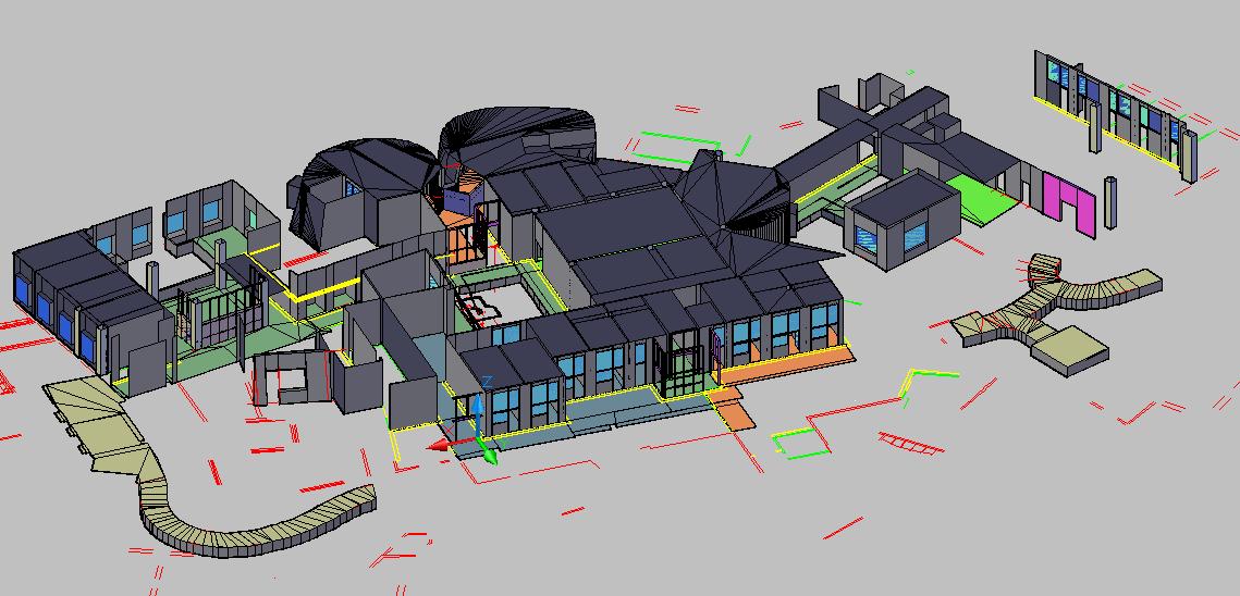
i. First Floor
See Student Street here
ii. Second Floor
- Around 70-80% of vertical walls, floors, and ceilings have been drawn.
- Light-holders have been drawn.
- Non-vertical geometries have not been attempted on this floor.
- Glass panels are still modeled the old way.
- External windows are not generated yet.
A screencap of the 2nd floor model.
back to top
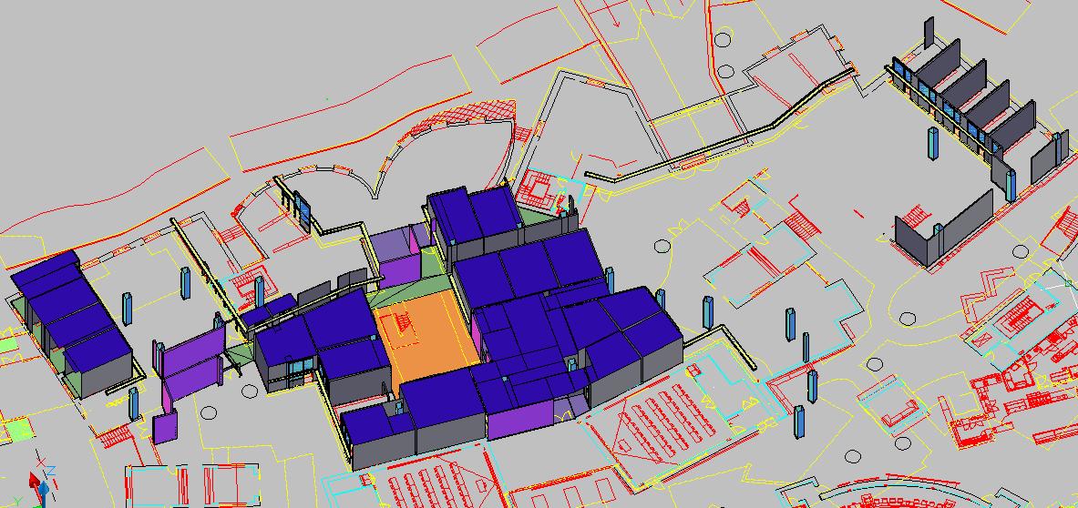
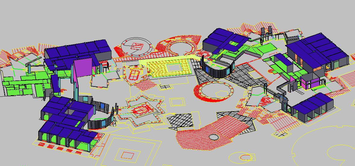
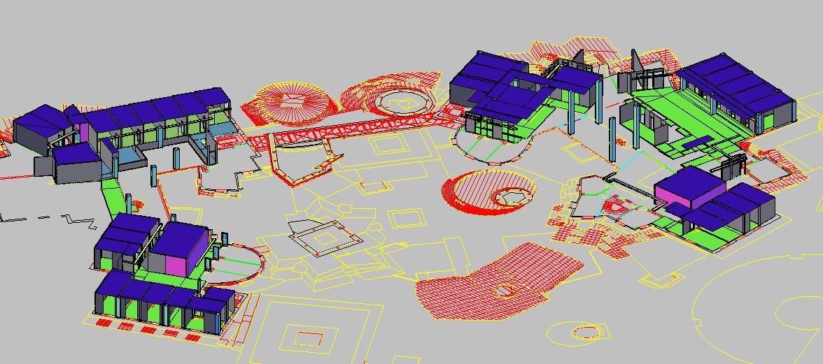
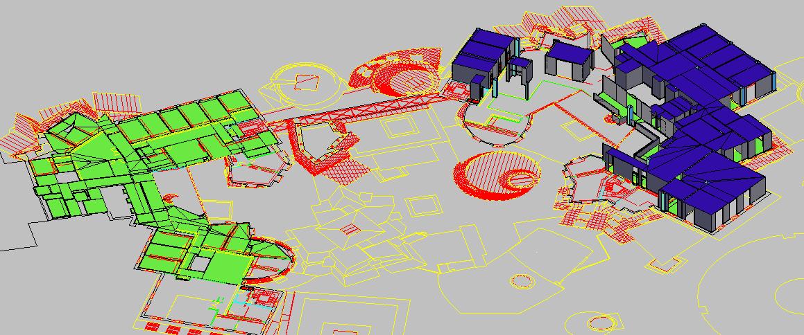
iii. Third Floor
- Over 90% of the vertical walls, floors, and ceilings have been drawn.
- Light-holders have been drawn.
- About half of the external windows have been drawn.
- Some non-vertical and non-planar geometries such as the ones in the 33x lab are in the model already. Although there are still a few non-vertical walls left to model.
- The barrel-shaped robotics lab will be exported directly from the Gehry files.
- Most of the glass panels are converted to the new way of modeling with the metal bars.
- Two out of the three stairwells going between two floors are modeled along with the railings.
A screencap of the 3rd floor model.
back to top
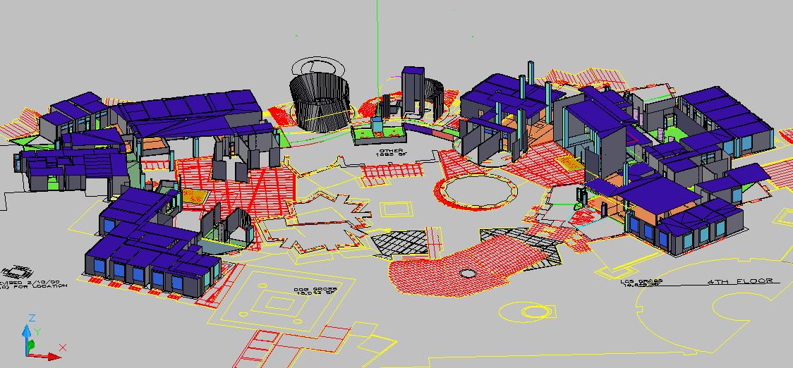
vi. Fourth Floor
- Over 90% of the vertical walls, floors, and ceilings have been drawn.
- Light-holders have been drawn.
- External windows have not been drawn.
- 80% of non-vertical planar walls drawn (Star Seminar Room and Kiva Room almost complete).
- 60-70% of non-vertical non-planar walls drawn (R&D pub mostly completely)
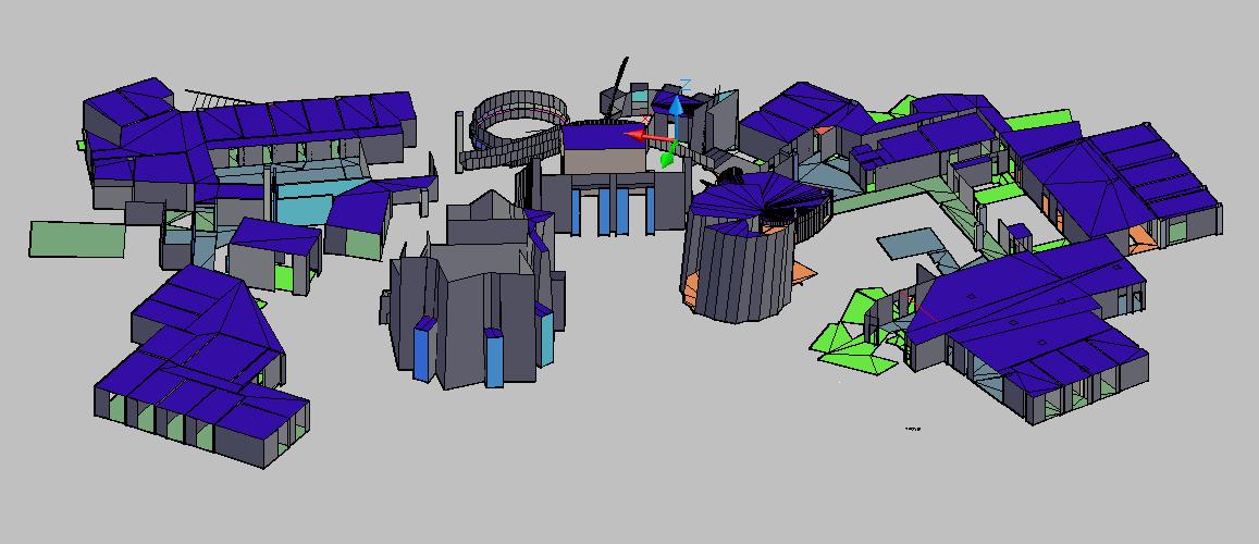
A screencap of the 4th floor model.
back to top
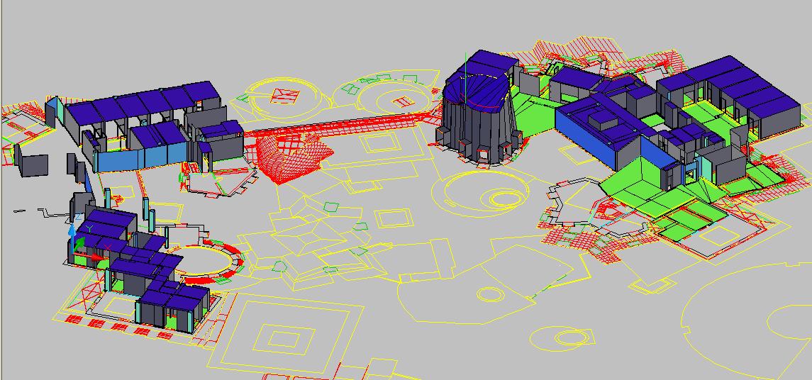
v. Fifth Floor
- Over 90% of the vertical walls, floors, and ceilings have been drawn.
- Light-holders have been drawn.
- External windows have been drawn.
- Non-vertical elements outside of offices are about 80% complete.
- Glass walls are still modeled the old way.
A screencap of the 5th floor model.
back to top
v. Sixth Floor
- Over 90% of vertical walls, floors, and ceilings have been drawn.
- Light holders have been drawn.
- About 50% of the external windows have been drawn.
- Non-vertical elements are about 80% complete.
- Glass walls are still modeled the old way.
A screencap of the 6th floor model.
back to top
v. Seventh Floor
- About 80% of vertical walls, floors, ceilings done.
- light-holders drawn.
- External windows not drawn.
- Glass walls still modeled in the old way, but there are not many of them.
- No non-verticals modeled, but there are not many of them.
A screencap of the 7th floor model.
back to top
v. Eighth Floor
- Vertical walls and ceilings 50% complete. Vertical floors over 90% complete.
- Light-holders are not drawn.
- External windows are not drawn.
- Glass walls are not modeled yet.
- No non-verticals modeled, but there are not many of them.
A screencap of the 8th floor model.
back to top
ix. Ninth Floor
- Vertical walls, floors, and ceilings 80-90% modeled.
- Light holders are not drawn.
- External windows are not drawn.
- Glass walls are modeled the old way.
- Curved lab on Gates side 90% complete. Curved lab on Dreyfoos side not modeled yet.
A screencap of the 9th floor model.
back to top